

12kV vs 24kV vs 40.5kV Switchgear Selection: BIL, Clearance & Insulation Coordination Guide
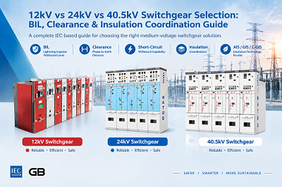
Subtitle: A voltage-class decision framework aligned with IEC 62271-1 / 62271-200
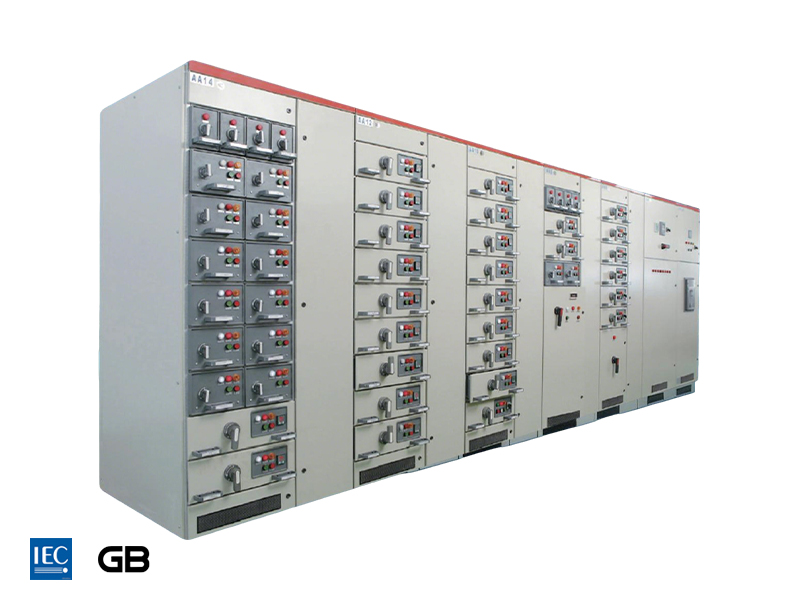
A 12 kV panel and a 24 kV panel look almost identical from the aisle for air-insulated types only. For C-GIS/GIS compact gas-insulated switchgear, physical dimensions can differ significantly. The real differences hide in the BIL numbers, clearance gaps, and creepage distances.
Selecting the wrong voltage class brings two major risks: insulation-coordination failures at commissioning, and non-compatible spare circuit-breakers years after project hand-over.
1. Why Voltage-Class Selection Matters More Than You Think
Medium-voltage switchgear covers rated voltages above 1 kV up to 52 kV, forming the backbone of substations, industrial facilities, renewable-energy plants and utility distribution networks. Among mainstream ratings, 12 kV, 24 kV and 40.5 kV are most widely deployed.
Selection is frequently oversimplified to one single question: What is the system voltage? In reality, voltage class is only the starting point. Safe 20-year service life relies on the holistic matching of BIL (Basic Insulation Level / lightning-impulse withstand level), clearances, creepage distances, short-circuit withstand capability and insulation technology.
Typical application positioning for the three voltage classes:
12 kV — Work-horse for urban distribution and small-scale commercial sites, corresponding to 10 kV system; most proven and widely adopted rating.
24 kV — Preferred solution for dense-city distribution and renewable-energy collection networks, corresponding to 20 kV system. Gaining growing acceptance across Asia and Europe.
40.5 kV — Interface for industrial and utility-scale power generation, corresponding to 35 kV system. Applied for large-scale solar PV collection, wind-farm collector substations and large captive power plants.
These correspondences follow IEC 60038 standard-voltage series. Equipment shall be selected against the system highest voltage rather than nominal system voltage.
For reference, the rated maximum voltage of MV switchgear is generally 1.2 times the nominal system voltage (1.15 times for 35 kV-class systems).
For instance, a 10 kV nominal system requires 12 kV-rated switchgear, and a 35 kV nominal system requires 40.5 kV-rated switchgear.
2. Core Parameters: BIL, Clearance & Short-Circuit Benchmarks
Nominal voltage defines operating stress; BIL defines dielectric withstand capability. Mismatch between these two is a frequent root-cause of specification errors.
Per IEC 62271-200, typical BIL reference values for air-insulated metal-enclosed switchgear are:
75 kVp for 12 kV
95-125 kVp for 24 kV (depends on selected insulation grade)
150-185 kVp for 40.5 kV
Important engineering note: For installation altitude above 1,000 m, air-insulated external insulation shall be corrected according to correction factors defined in IEC 62271-1 and GB/T 11022.
Do not apply the simplified empirical rule of “1% clearance increase per 100 m altitude gain” directly for engineering design.
Minimum phase-to-earth clearances are jointly determined by rated voltage and selected insulation level. All actual values shall be validated against official type-test reports.
| Parameter | 12kV | 24kV | 40.5kV |
|---|---|---|---|
| Rated voltage (IEC 60038) | 12 kV | 24 kV | 40.5 kV |
| BIL (lightning impulse withstand) | 75 kVp | 95–125 kVp | 150–185 kVp |
| Power-frequency withstand (1 min) | 28 kV / 42 kV | 50 kV / 65 kV | 80 kV / 95 kV |
Clearance, Short-Circuit Capability and Engineering Verification Notes
| Parameter | 12kV | 24kV | 40.5kV |
|---|---|---|---|
| Phase-to-earth minimum clearance | ≈100 mm | ≈180 mm | ≈290 mm |
| Typical short-circuit breaking current | 16–31.5 kA | 20–31.5 kA | 25–40 kA |
Notes:
The slash "/" within power-frequency withstand values represents two alternative insulation grades defined by IEC 62271-1.
For example, 12 kV equipment can be specified for standard insulation 28 kV (corresponding to BIL 75 kVp), or enhanced-grade insulation 42 kV (corresponding to BIL 95 kVp).
Clearance figures above are typical reference benchmarks under IEC 62271-200. Real-world values vary with selected insulation level and must be cross-checked against type-test reports.
Short-circuit breaking currents listed are typical ranges; final values shall be derived from project-specific system short-circuit calculation.
Engineering note: Specifying equipment purely by rated voltage is insufficient. Insulation-coordination verification against BIL and clearance requirements of IEC 62271-200 is mandatory.
Many projects encounter unexpected insulation-related issues only at commissioning due to missing this verification step.
3. Insulation Technology Routes: AIS, GIS & C-GIS
Medium-voltage switchgear can be grouped into three major insulation-technology families, each showing different suitability for different voltage classes.
Air-Insulated Switchgear (AIS)
AIS uses ambient air as the primary insulating medium for live parts.
Key strengths include:
Lower capital expenditure.
Straightforward maintenance.
Mature technology with massive field-service track record.
However, AIS also has several limitations:
Large floor-space occupation.
Performance is susceptible to site pollution including dust, high humidity and salt-laden atmosphere.
Gas-Insulated Switchgear (GIS / C-GIS)
GIS encapsulates all live components inside hermetically-sealed metallic enclosures filled with insulating gas.
For identical main-circuit configuration, GIS footprint can be up to 90% smaller compared with equivalent AIS switchgear.
Its immunity against harsh ambient conditions makes it ideal for:
Urban substations.
Underground distribution facilities.
Data-centre power systems.
SF₆-Free Gas Insulation Technology
SF₆ is a potent greenhouse gas subject to tightening global environmental regulations.
IEC 63360:2025 defines quality requirements and test methods for SF₆-alternative gases applied within electrical power equipment.
The transition toward SF₆-free insulation technologies is accelerating due to environmental compliance requirements and increasing demand for sustainable power infrastructure.
Market Trend of C-GIS Technology
Market research projections indicate that the global C-GIS market was valued at approximately USD 7,527 million in 2025 and is forecasted to reach USD 14,430 million by 2032, representing a CAGR of 9.9% during 2026–2032.
Market growth is mainly driven by:
SF₆-free environmental compliance requirements.
Compact substation design demand.
Digital monitoring and smart-grid applications.
NATUS SF₆-Free Gas-Insulated Solution Example
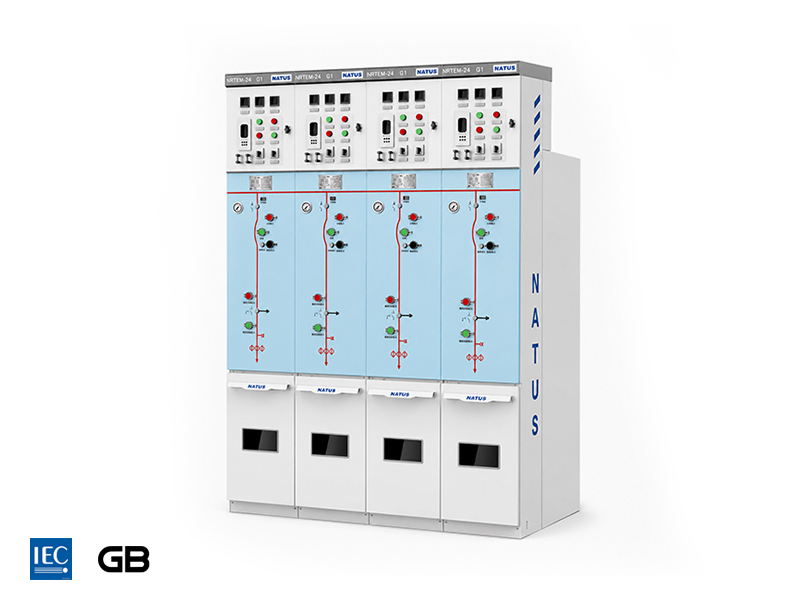
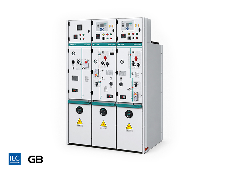
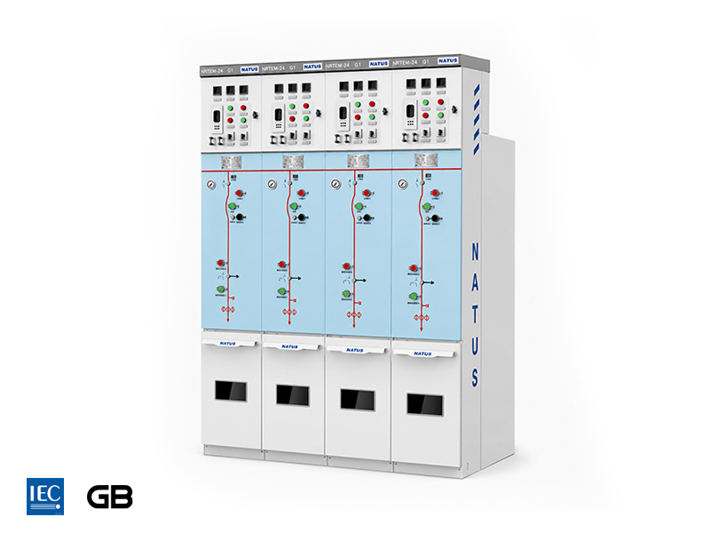
NATUS provides NRTem-24 kV SF₆-free gas-insulated ring-main-unit (RMU).
This product adopts a fully-welded stainless-steel gas tank, IP67 enclosure protection, IAC (Internal Arc Classification) 20 kA/1 s internal-arc withstand capability and rated current of 630 A.
It delivers a field-proven SF₆-free solution for projects with explicit low-carbon environmental targets.
4. A Structured Decision Framework for Voltage-Class Selection
Equipment selection is not a simplistic “higher rating is always better” exercise, but a systematic logical decision workflow.
Step 1: Establish System-Parameter Baseline
The first step is to obtain the system highest voltage rather than nominal voltage from utility authorities or project-design documentation.
The system highest voltage defines the minimum rated voltage requirement of the switchgear.
For example, a 13.8 kV nominal system generally requires 17.5 kV-rated switchgear to cater for voltage transients and operational over-voltages.
This step establishes the minimum threshold for equipment rated voltage selection.
Step 2: Short-Circuit-Current Verification
The switchgear short-circuit withstand rating shall be greater than or equal to the calculated prospective fault current at the installation location.
Typical medium-voltage short-circuit withstand levels range from 16 kA to 50 kA.
The calculation shall consider multiple system factors, including:
Utility fault level.
Transformer impedance.
Generator short-circuit contribution.
Motor-feedback current.
Even if the voltage class matches perfectly, the equipment remains unsafe if short-circuit verification fails.
Step 3: Insulation-Coordination & BIL Verification
After confirming the voltage class and short-circuit capability, insulation coordination must be verified.
The required parameters include:
Basic Insulation Level (BIL).
Power-frequency withstand voltage.
External insulation creepage distance.
Clearance distance requirements.
These values shall be determined according to:
System highest voltage.
Installation altitude.
Pollution severity class.
Applicable IEC standards.
Where site altitude exceeds 1,000 m, external insulation parameters shall be corrected according to applicable standards.
This step converts an abstract voltage-class selection into measurable insulation-performance requirements.
Step 4: Installation-Environment Assessment & Insulation-Technology Route
Site environmental conditions play a decisive role when choosing between AIS, GIS and C-GIS solutions.
Engineers should evaluate the following factors:
Indoor or outdoor installation conditions.
Ambient temperature range.
Humidity level.
Dust contamination.
Salt spray exposure.
Corrosive gas conditions.
Installation altitude.
Available floor area.
For space-limited applications such as urban substations, underground power rooms and data centres, the compact advantages of GIS/C-GIS become highly valuable.
Compared with traditional AIS solutions, GIS and C-GIS provide improved environmental resistance and reduced installation footprint.
Step 5: Safety Rating & Future-Expansion Capability
Internal-arc protection represents fundamental personnel-safety protection and cannot be treated as an optional feature.
Complete IAC marking syntax follows:
IAC accessibility-code + test-current / test-duration
The accessibility codes are defined as follows:
A — Authorized-personnel-only access.
F — Front accessibility.
L — Lateral accessibility.
R — Rear accessibility.
For example, marking:
IAC A-FLR 20 kA/1 s
means the equipment is safe for authorized personnel access from front, side and rear under a 20 kA, 1-second internal-arc test condition.
Example of High-Voltage C-GIS Application
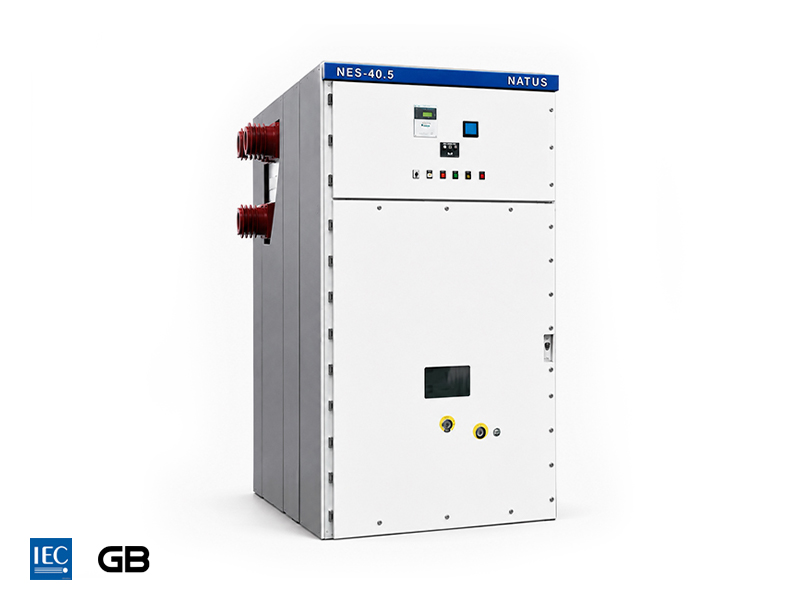
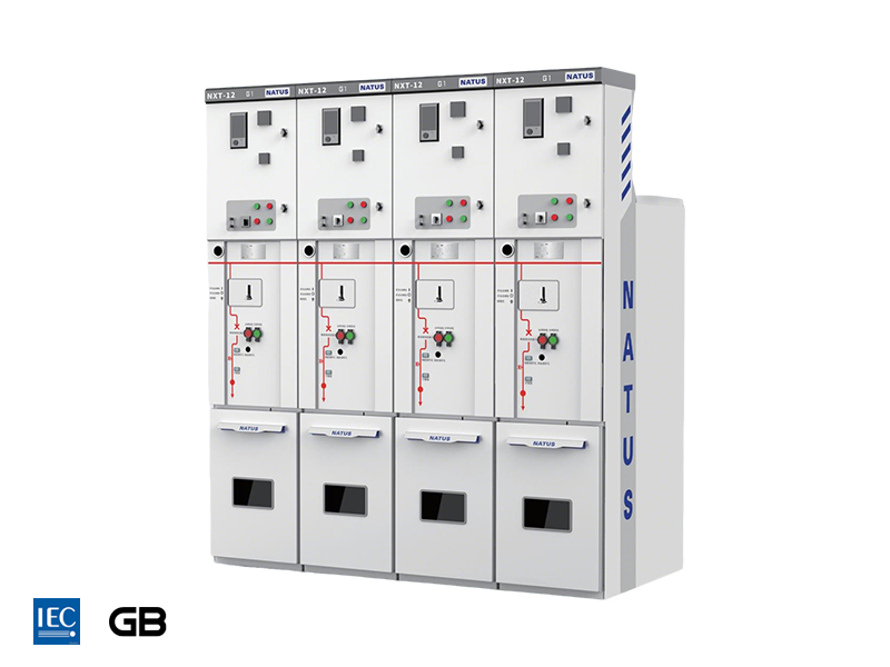
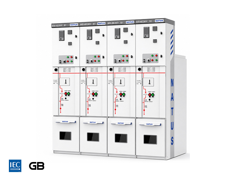
As a product example, NATUS NXTs-40.5 C-GIS adopts a three-phase common-tank architecture.
The equipment supports:
Maximum rated current up to 3,150 A.
Rated short-circuit breaking current of 31.5 kA.
Top-entry and side-busbar extension configurations.
The design is suitable for high-specification substations and heavy-duty industrial power applications.
5. Common Selection Pitfalls
Pitfall 1: Specify Equipment Only by Nominal Rated Voltage
Selecting switchgear only according to nominal voltage is one of the most common engineering mistakes.
Correct voltage rating alone cannot guarantee safe operation if BIL, insulation coordination or short-circuit withstand capability is mismatched with actual system conditions.
A complete technical evaluation should include:
System highest voltage verification.
Lightning impulse withstand level (BIL).
Power-frequency withstand capability.
Short-circuit withstand calculation.
Pitfall 2: Regard 40.5 kV Hardware as “Up-Rated 24 kV Switchgear”
40.5 kV-class equipment is not simply an upgraded version of 24 kV switchgear.
It uses completely different:
Insulation layout.
Type-test requirements.
Clearance criteria.
Dielectric design principles.
Independent engineering evaluation is mandatory when selecting equipment between different voltage classes.
Pitfall 3: Neglect Electrical Margin for Future System Expansion
Sizing equipment only according to present-day load conditions may create limitations during future expansion.
Potential risks include:
Insufficient busbar ampacity.
Future short-circuit level exceeding equipment withstand capability.
Limited upgrade flexibility.
A properly designed switchgear system should consider long-term power-demand growth and expansion requirements.
Pitfall 4: Focus Only on Initial Purchase Price
The lowest purchase price does not always represent the most economical solution throughout the equipment lifecycle.
Total cost of ownership should include:
Installation cost.
Operation and maintenance expenses.
Potential plant downtime.
Spare-part inventory requirements.
Gas-handling and environmental compliance costs.
Lifecycle costs often become more significant years after commissioning.
6. International Project Inquiry Checklist
Providing complete project information to switchgear manufacturers can significantly improve proposal accuracy and technical alignment.
Before requesting a technical quotation, customers should prepare the following information:
System highest voltage.
Rated continuous current.
Prospective short-circuit current level at installation point.
Rated frequency.
Number of incoming and outgoing feeder circuits.
Busbar configuration and arrangement.
Indoor or outdoor installation conditions.
Site environmental profile, including temperature range, humidity, altitude and pollution-severity class.
Required enclosure IP protection grade.
Required Internal-Arc Classification (IAC), including accessibility codes.
Protection scheme and communication / SCADA requirements.
Applicable standards, such as IEC, GB or IEEE.
Mandatory product certifications.
Future expansion requirements.
7. Conclusion
Selecting between 12 kV, 24 kV and 40.5 kV switchgear is fundamentally a system-engineering decision rather than a simple voltage-matching exercise.
The recommended selection workflow is:
Start from system highest-voltage definition.
Apply short-circuit-capacity verification as a mandatory constraint.
Complete BIL-based insulation coordination analysis.
Balance installation environment requirements with lifecycle cost.
Select the optimum combination of voltage rating and insulation technology.
NATUS Electric inherits technical expertise from Germany-based NATUS Group and operates as its Asia-Pacific R&D and manufacturing hub.
The product portfolio covers 12 kV to 40.5 kV medium-voltage switchgear solutions, including:
GIS / C-GIS.
Ring-main units.
Eco-friendly gas-insulated equipment.
These solutions serve power utilities, industrial facilities, renewable-energy projects and infrastructure applications.
For datasheets, configuration suggestions or project-tailored selection support, please contact NATUS Electric and provide your system parameters and site-installation requirements.
Reference Standards
Note: IEC and national standards are subject to revision. Always apply the latest valid edition for real-world engineering projects.
IEC 62271-1:2017 — High-voltage switchgear and controlgear, Part 1: Common specifications.
IEC 62271-100 — High-voltage alternating-current circuit-breakers.
IEC 62271-200:2011 — AC metal-enclosed switchgear and controlgear for rated voltages above 1 kV and up to and including 52 kV.
IEC 60038 — IEC standard voltages.
IEC 63360:2025 — Specification of gases alternative to SF₆ for use in electrical power equipment.
GB/T 11022 — Common specifications for high-voltage switchgear and controlgear standards.