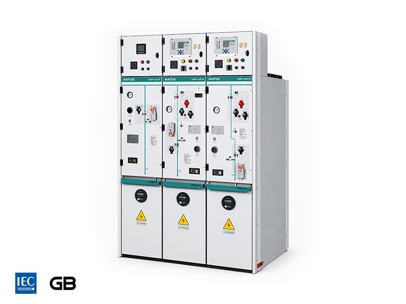
The NRTs-40.5 is a 40.5kV SF6 gas-insulated ring main unit (RMU) developed by NATUS Electric for medium- and high-voltage power distribution applications. It features an IP67-rated 304 stainless-steel gas tank, IAC 25 kA/1 s internal arc protection, intelligent condition monitoring, and flexible top or side expansion. These features support compact power distribution configurations for substations, industrial facilities, and renewable energy projects, subject to the project’s electrical ratings and operating requirements.

The 40.5kV SF6 Gas Insulated RMU adopts a 304 stainless-steel laser-welded gas tank with an annual leakage rate ≤0.25‰. The fully sealed design provides excellent resistance to condensation, salt mist, corrosion, and UV aging, ensuring long-term reliable GIS operation.


Circuit Breaker Unit
| Basic Parameters | ||
| Rated Voltage | kV | 40.5 |
| Power Frequency Withstand Voltage | kV | 95/118 |
| Lightning Impulse Withstand Voltage | kV | 190/220 |
| Rated Current | A | 630 |
| Rated Short-Circuit Breaking Current | kA | 20(25) |
| Rated Short-Circuit Making Current | kA | 50(63) |
| Rated Short-Time Withstand Current | kA/s | 20(4) / 25(4) |
| Mechanical Life | Time | Circuit Breaker: 10,000 / Isolation: 5,000 / Earthing: 5,000 |
Load Switch Unit
| Basic Parameters | ||
| Rated Voltage | kV | 40.5 |
| Power Frequency Withstand Voltage | kV | 95/118 |
| Lightning Impulse Withstand Voltage | kV | 190/220 |
| Rated Current | A | 630 |
| Rated Short-Circuit Breaking Current | kA | 20(25) |
| Rated Short-Circuit Making Current | kA | 50(63) |
| Rated Short-Time Withstand Current | kA/s | 20(4) / 25(4) |
| Mechanical Life | Time | Circuit Breaker: 10,000 / Isolation: 5,000 / Earthing: 5,000 |
Circuit Breaker Unit (Busbar Grounding)
| Basic Parameters | ||
| Rated Voltage | kV | 40.5 |
| Power Frequency Withstand Voltage | kV | 95/118 |
| Lightning Impulse Withstand Voltage | kV | 190/220 |
| Rated Current | A | 630 |
| Rated Peak Current | kA | 50(63) |
| Rated Short-Time Withstand Current | kA/s | 20(4) / 25(4) |
| Mechanical Life | Time | Load: 5,000 / Earthing: 5,000 |
Commonly Used Standards
| Basic Parameters | |
| IEC 62271-200:2011 | High-voltage switchgear and controlgear - Part 200: AC metal-enclosed switchgear and controlgear for rated voltages above 1kV and up to and including 52kV |
| GB/T 3906-2006 | 3.6kV~40.5 kV AC metal-enclosed switchgear and controlgear |
| GB/T 11022-2011 | Common specifications for high-voltage switchgear and controlgear standards |
| GB/T 1984-2014 | High-voltage alternating-current circuit breakers |
| GB/T 3804-2017 | High-voltage alternating-current switches for rated voltage above 3.6kV and less than 40.5 kV |
| GB/T 1985-2014 | High-voltage alternating-current disconnectors and earthing switches |
| IEC 62271-105 | High-voltage switchgear and controlgear - Alternating-current switch-fuse combinations |
| IEC 62271-103 | High-voltage switchgear and controlgear - Switches for rated voltages above 1kV and up to and including 52kV |
| IEC 60265-1 | High-voltage switches - Part 1: Switches for rated voltages above 1kV and less than 52kV |
| DL/T 404-2018 | AC metal-enclosed switchgear and controlgear |
| DL/T 593-2016 | Common specifications for high-voltage switchgear and controlgear standards |
General Characteristics
| Basic Parameters | |
| Altitude | ≤ 2000 m |
| Ambient temperature | -25°C to +40°C |
| Daily average temperature | ≤ 35°C |
| Relative humidity | Daily average ≤95%; monthly average ≤90% |
| Pollution degree | II / Ⅲ / Ⅳ (as required by project conditions) |
| Installation location | Indoor, free from severe vibration, corrosive gas and conductive dust |
Operating Conditions
| Basic Parameters | |
| Ambient air temperature | Maximum: +40°C; minimum: -25°C; average over 24h: ≤35°C |
| Humidity | Daily average relative humidity ≤95%; monthly average relative humidity ≤90% |
| Altitude | ≤ 2000 m |
| Installation environment | Indoor installation; no obvious vibration, no corrosive or explosive gas, and no severe dust pollution |
| Seismic intensity | Suitable for normal substation operating environment |
Cabinet Construction Method
| Basic Parameters | |
| Top-Expansion Cabinet Combination Method | Cabinets are combined through the top-expansion interface to realize busbar extension and cabinet-to-cabinet connection. |
| Side-Expansion Cabinet Combination Method | Cabinets are combined through the side-expansion interface to support flexible line-up configuration. |